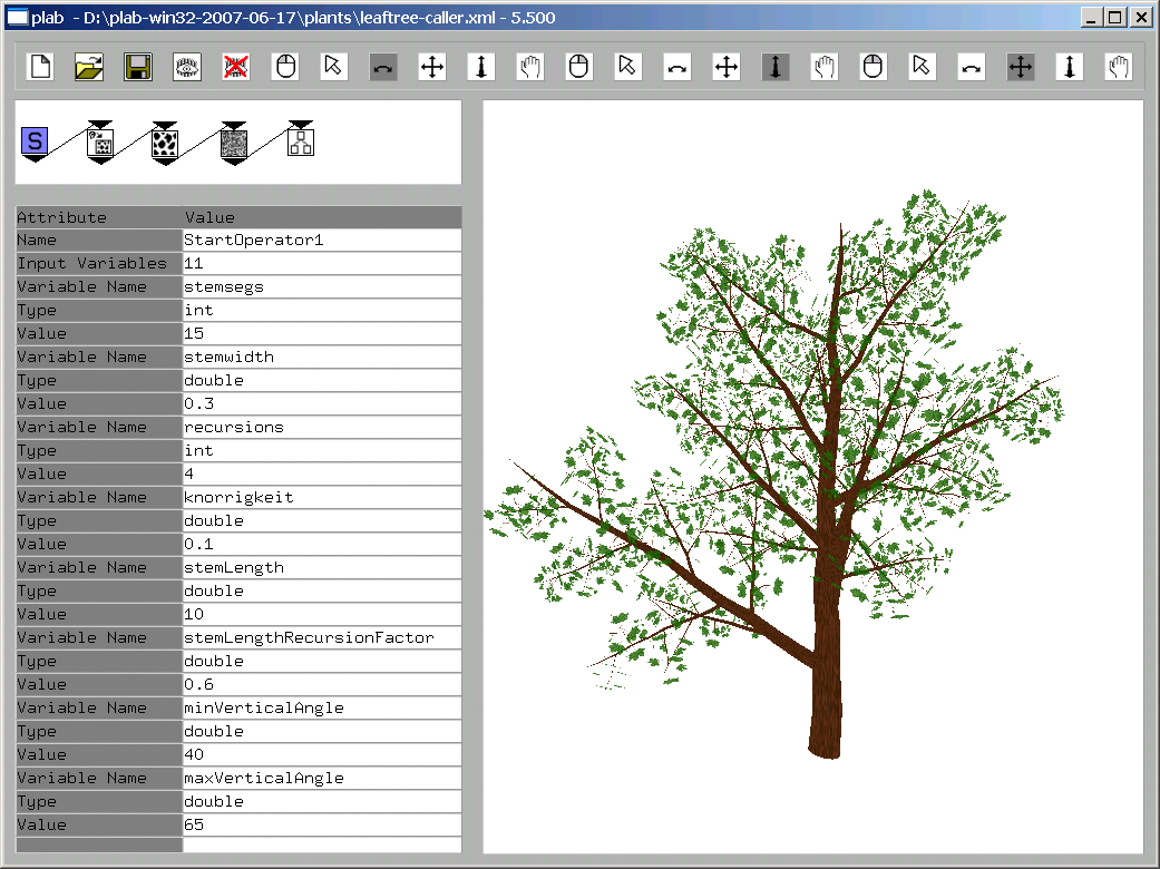
The screenshot above shows plab. It executes programs called model graphs. The name model graph stems from the fact that these programs are graphs that create models. The topmost element of the window is the toolbar . The model graph is edited in top left part of the window, the attribute editor is edited below that, and the result of running SceneFactory is displayed to the right. The following text will help you understand how a model graph creates geometry.
The model graph above consists of four nodes that are executed top-down. While this is not true in general, it will suffice until we close examine execution order in the next chapter. There are four nodes: StartOperator, RoughTextureGenerator, MultiplyAlongVectorOperator and CubeOperator.
StartOperator defines some central parameters, in this case, the number of cubes to create. RoughTextureGenerator creates a texture by scattering texel colors between minimum and maximum colors. MultiplyAlongVector multiplies the cubes created by CubeOperator and applies the texture created by RoughTextureGenerator. MultiplyAlongVector creates as many cubes as requested in StartOperator.
Nodes are created using the context menu. To connect two nodes, drag the target node onto the source. Dragging the target node onto the source again will remove the edge. The context menu of a node allows you to delete or copy nodes.
You can read more about these operators in the reference section of this manual. The reference section consists of three parts describing operators, components, and texture generators. Texture generators do what their name implies. Components require textures and create geometry. All other nodes are operators.
Next Chapter: Traversal rules